222021-10
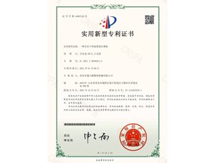
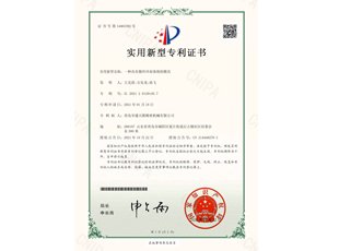
An injection molding machine with a blanking device: the utility model discloses an injection molding machine with a blanking device, which comprises a bottom plate, the upper surface of the bottom plate is fixedly connected with two fixed seats, and the top of the fixed seat is fixedly connected with an extruder. Out of the barrel, an extrusion screw is movably connected to the inner wall of one side of the extrusion barrel, a bracket is fixedly connected to the upper surface of the bottom plate, a first motor is fixedly connected to the upper surface of the bracket, and one end of the extrusion screw is connected to the first motor. One end of the output shaft is fixed, and a mounting frame is fixedly connected to the upper surface of the bottom plate. The utility model not only enables the stirring rod to fully stir the injection molding raw materials, prevents the injection molding raw materials from being coarse in texture, and improves the quality of the products produced by the mold, but also can automatically extrude the raw materials from the extrusion barrel through the rotation of the extrusion screw, thereby improving the injection molding efficiency. It is also possible to enable the staff to observe the stirring situation of the injection molding raw materials in the mixing tank at any time through the window, so that the raw materials can be put into the mixing tank in time, and the mixing efficiency of the injection molding materials can be improved.
222021-10
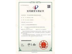
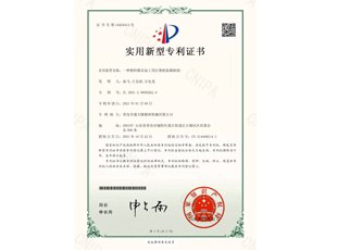
A cleaning device that can quickly clean up wastes of plastic injection molding machines: The utility model discloses a cleaning device that can quickly clean up wastes of plastic injection molding machines, comprising a support plate and an electric control box, the upper surface of the electric control box is fixedly connected with a Two electric slide rails, an electric slider is slidably connected in the electric slide rail, a hot-melt box is fixedly connected between the two electric sliders, a feed hopper is fixedly connected to the top of the hot-melt box, and one side of the hot-melt box is fixed A feeding pipe is connected, the top of the support plate is fixedly connected with an injection molding box, one side of the outer wall of the bottom of the injection molding box is fixedly connected to one side of the outer wall of the top of the electric control box, and one side of the injection molding box is provided with a connecting pipe, and the connecting pipe The other end of the injection molding box is plugged with the other end of the feeding pipe, and the bottom of the injection box is fixedly connected with a discharge hopper. The utility model can quickly clean up the waste material in the plastic injection molding machine, ensure the effect and quality of the subsequent injection molding, and can also avoid the phenomenon that the injection molding liquid blocks the feeding pipe, and ensure the normal progress of the injection molding work.
222021-10
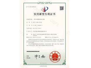
An injection molding machine with a clamping mechanism: the utility model discloses an injection molding machine with a clamping mechanism, comprising a casing, the inner walls of both sides of the casing are fixedly connected with a fixing seat, and one side of the fixing seat is fixed A plurality of mounting seats are connected, one side of the mounting seat is movably connected with a cylinder, one end of the cylinder piston rod is fixedly connected with a connecting ring, one side of the mounting seat is movably connected with a fixing block, and one side of the fixing block is fixedly connected with a first Three connecting rods, one side of the third connecting rod is movably connected with a sleeve, and one end of the third connecting rod is movably connected with a second connecting rod. The utility model can not only press the mold by the second pressing block and the first pressing block, but also can clamp the molds of different sizes in the injection molding machine, which improves the flexibility of the device, and simultaneously, the upper mold and the lower mold can be adjusted by pulling the lifting ring. The mold can be moved, which is convenient for the staff to replace the template, and it is also convenient for the staff to observe the working conditions inside the device through the viewing window, which improves the convenience of the device.
222021-10
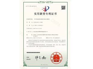
An injection mold that can quickly replace a live insert core block: The utility model discloses an injection mold that can quickly replace a live insert core block, comprising a lower clamping plate and an upper clamping plate, the upper surface of the lower clamping plate is fixedly connected with a strip The upper surface of the stripping plate is provided with a plurality of first installation holes, the first installation holes are movably connected with a guide column, the top of the guide column is fixedly connected with a lower cavity mold, and the upper surface of the lower cavity mold is provided with a cavity. The bottom of the cavity is provided with a guide groove, and the cavity is provided with a core block. The utility model can not only change the shape of the injection mold by replacing the core blocks of different styles, save a lot of time, and improve the efficiency of injection molding of the mold, but also can automatically lift the core through the drive of the motor when the injection molding of the mold is completed. It is convenient for the disassembly of the injection mold core block, and it can also provide a buffer for the mold injection, reduce the pressure in the process of mold injection, and improve the injection effect of the mold.
222021-10
A mold with a circulating cooling system: The utility model discloses a mold with a circulating cooling system, comprising a lower clamping plate and an upper clamping plate, a plurality of guide columns are fixedly connected to the bottom inner wall of the lower clamping plate, and one side of the guiding column is A lower cavity mold is movably connected, an upper cavity mold is fixedly connected to the bottom of the upper splint, and the upper cavity mold is in contact with the lower cavity mold, and one side of the upper cavity mold and the lower cavity mold is provided with a mold cavity, And the two mold cavities are in contact, two cooling pipes are provided on one side of the upper cavity mold and the lower cavity mold, and a shunt box is fixedly connected to one side outer wall of the upper cavity mold and the lower cavity mold. The utility model can not only control the amount of water in the cooling pipe through the slider, it is convenient for the staff to control the temperature of the mold after cooling, and the quality effect of the product is improved, and at the same time, the backflow of the cooling water can be avoided through the baffle plate, and the convenience of the device is improved. It can also buffer the lower mold cavity during the movement process by the spring, which improves the stability of the device.
222021-10
A mold taking mechanism for an injection molding machine for plastic mold processing: The utility model discloses a mold taking mechanism for an injection molding machine for plastic mold processing. A casing is connected, a bracket is fixedly connected to the upper surface of the mounting frame, a hydraulic cylinder is fixedly connected to the upper surface of the bracket, a fixed base is fixedly connected to one outer wall of the casing, and one side of the fixed base and the casing are A plurality of first sliding holes are opened, one side of the first sliding holes is movably connected with a connecting shaft, and one side of the fixed base is fixedly connected with a push rod. The utility model can not only push out the finished product in the lower cavity mold through the ejector column, so that the device can automatically take the mold and improve the production efficiency of the device, at the same time, the device can be protected by a transparent protective cover to avoid the damage of the device caused by external impact. It is also possible to adjust the height of the telescopic foot plate, so that the universal wheel can be in contact with the ground, and it is convenient for the staff to move the device.
